
Navigation aid remote control and telemetry system optimization
1. System overview
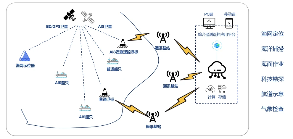
The navigation-light remote control and telemetry system is an intelligent management platform based on Internet of Things technology and BeiDou communication and positioning. It addresses the low efficiency, high cost and risk of conventional navigation-aid inspections. Remote real-time monitoring, data analysis and coordination between multiple terminals provide precise, all-weather management of navigation equipment and improve the efficiency and safety of maritime operations and maintenance.
2. Core technology architecture
Internet of Things technology: sensors collect navigation-aid status in real time, including light brightness, battery level and position offset, and automatically send data back. Networking of multiple devices supports complex waterway environments.
BeiDou communication and positioning: high-precision satellite positioning continuously updates and tracks navigation-aid locations. Stable data transmission remains available outside public-network coverage, supporting system reliability.
Cloud collaboration: data is stored centrally in a cloud platform, supporting user-permission management across regions and multiple organizational levels.
3. Core functional modules
Desktop management software: a visual map displays navigation-aid distribution, equipment status and alarms in real time, with one-click control commands. Mobile monitoring software: view navigation-aid data anywhere, receive anomaly notifications and handle emergencies from a mobile device.
4. Remote-control and telemetry navigation lights
Navigation lighting system performance
◆ Monitoring coverage: coastal waters and areas with mobile-network coverage (BeiDou remote control and telemetry can be provided where mobile signals are unavailable).
◆ Positioning: autonomous BDS/GPS positioning.
◆ Communication: primarily 4G, with SMS as a backup.
◆ Positioning accuracy: 5~15 m.
◆ Monitoring interval: adjustable from 1 minute to 24 hours.
◆ System capacity: 2000 networked monitoring terminals (department-level server).
◆ Alarm response: less than 20 seconds.
◆ Historical data: retained for more than 1 month.
Remote-control and telemetry transmission and operating diagram
5. Navigation lighting system technical specifications
(1) Navigation-light electrical performance
◆ Supply voltage: 8~30VDC
◆ Sleep current: less than 20 MA (12V);
◆ Static operating current: less than 100 MA (12V);
◆ Dynamic operating current: less than 500 MA (12V);
(2) Interfaces and transmission rates
◆ Designed with internationally used standard communications interfaces.
◆ Transmission rate: bps~ bps.
(3)MTBF:≥10000h
6. Navigation light data collection
The monitoring terminal collects navigation-light data, lightship and light-buoy position and impact information, power-supply data and information from auxiliary facilities. The system should support the following main telemetry functions.
(1) Telemetry of buoy latitude, longitude and speed, with calculation of base-point offset and recording of movement tracks.
(2) Telemetry of navigation-light flash period, flash mode or light characteristic (preset and current characteristics).
(3) Telemetry of navigation-light operating status (main/secondary, normal/abnormal).
(4) Telemetry of navigation-light power-supply status (open/closed circuit, operating current and voltage).
(5) Telemetry of navigation-light battery voltage.
A. Navigation light data
Light operating voltage: accuracy class 0.5
Light operating current: accuracy class 0.5
Light characteristic (light/dark duration S): resolution <0.01S
Navigation-light daylight threshold: 50-200Lux;
B. Horizontal position of vessels, lightships and buoys
Longitude: resolution 0.0001’ (WGS84 coordinate system)
Latitude: resolution 0.0001’ (WGS84 coordinate system)
Speed: buoy movement in nautical miles/hour
7. Navigation light power supply
Battery voltage: accuracy class 0.5
Operating current: accuracy class 0.5
The terminal continuously collects data and monitors navigation-light operation in real time so it can raise an immediate alarm after a fault. The collection rate should be ≥1 time/minute.
8. Scheduled transmission of navigation light data
The monitoring terminal periodically sends data to the central station so that the monitoring center can track the light's operating status over that period. The monitoring center can set the transmission interval.
9. Navigation light query response
After receiving a query, the navigation-aid monitoring terminal sends data to the monitoring center in a timely manner.
Automatic alarms
The system automatically checks preset ranges and immediately sends alarm information when a navigation aid is abnormal or collected data exceeds a preset limit:
(1) The terminal detects and automatically alarms when a buoy exceeds its displacement range (adjustable to 10 m, 20 m, 30 m, etc.), maximum drift range, or when a vessel leaves its navigation range. Automatic tracking during alarms, with historical track storage and playback, helps recover missing navigation aids.
(2) Power-supply undervoltage and overvoltage alarms, with configurable and editable thresholds.
(3) Abnormal flashing alarms (incorrect flash mode or light characteristic).
(4) Abnormal light-output alarms, including daytime illumination, failure to illuminate at night or insufficient available lamps.
The monitoring terminal detects these alarms and sends them to the monitoring center, alerting duty personnel through sound, images or SMS. The monitoring-center backend can also raise terminal-timeout and communications-fault alarms.
10. Navigation light sleep and power saving
After sending data or receiving a monitoring-center instruction, the terminal automatically enters power-saving sleep, drawing less than 20MA. It can still receive queries and remote-setting commands and wake immediately.
The detection circuit remains active during power-saving sleep. Displacement, drift, impact, abnormal light operation or out-of-range parameters immediately wake the monitoring terminal and trigger an alarm to the monitoring center.
11. Navigation light remote control
The monitoring terminal receives remote commands from the central station and controls navigation aids or other facilities accordingly. It supports the following remote settings for the navigation light and monitoring RTU:
(1) Remotely restart and log in to the monitoring RTU.
(2) Stop data uploads from the monitoring RTU and remove timed-out RTUs from the GIS map.
(3) Remotely change RTU operating modes, including login, polling, addressed queries and alarms.
(4) Remotely set data-upload intervals for each RTU operating mode.
(5) Remotely configure RTU alarm conditions, including displacement, drift, overvoltage/undervoltage, abnormal light output and the last available lamp count.
(6) Remotely set alarm sensitivity for each navigation light to reduce false alarms.
(7) Where a navigation light has a communications interface, the monitoring terminal can use the standard interface to change its light characteristic, daylight threshold and other parameters.
Solution diagrams
Original Chinese document · DOCX
Original Chinese document
航标遥控遥测系统优化方案
一、系统概述
航标遥控遥测系统是基于物联网技术与北斗通信定位技术的智能化管理平台,旨在解决传统航标巡检效率低、成本高、风险大的痛点。通过远程实时监控、数据分析和多终端协同,实现对航标设备的全天候精准化管理,大幅提升海事运维效率与安全性。
二、核心技术架构
物联网技术;通过传感器实时采集航标设备状态(如灯光亮度、电池电量、位置偏移等),实现数据自动回传。支持多设备组网,覆盖复杂水域环境。
北斗通信定位技术;利用北斗卫星系统的高精度定位功能,确保航标位置实时更新与追踪。在无公网信号区域仍可稳定传输数据,保障系统可靠性。
云端协同管理;数据集中存储于云端平台,支持跨区域、多层级用户权限管理。
三、核心功能模块
电脑端管理软件:提供可视化地图界面,实时显示航标分布、设备状态及告警信息,支持一键下发控制指令。 手机端监控软件:随时随地查看航标数据,接收异常推送,支持移动端应急处理。
四、遥控遥测航标灯产品简介
航标灯系统性能指标
◆监控范围:沿海海域,以及移动网络覆盖区域内(无移动网络信号地方可以提供北斗遥控遥测)。
◆定位方式:BDS/GPS自主定位方式。
◆通信方式:4G为主、短信方式为辅。
◆定位精度:为5~15米。
◆监控间隔:1分钟~24小时可设置。
◆系统容量:2000个监控终端入网(处级服务器)。
◆报警响应:小于20秒。
◆历史数据:历史数据存放时间大于1个月。
遥控遥测传输方式及工作原理图
五、航标灯系统技术指标
(1)航标灯电气性能指标
◆电源电压:8~30VDC
◆休眠状态电流:小于20 MA(12V);
◆静态工作电流:小于100 MA(12V);
◆动态工作电流:小于500 MA(12V);
(2)接口及传输速率
◆按国际通用的标准通信接口类型设计。
◆传输速率为:bps~ bps。
(3)MTBF:≥10000h
六、航标灯采集数据
监控终端采集航标灯的各种数据信息,主要包括:灯器的数据信息、灯船、灯浮标的位置信息及撞击信息、供电系统数据信息及其他辅助设施的数据信息。本系统应能对航标灯实施以下主要遥测项目
(1)能遥测浮标经纬度和运动速度,并计算基点偏移值。移动时记录轨迹。
(2)能遥测航标灯闪光周期、闪光方式或灯质(预设灯质、当前灯质)
(3)能遥测航标灯工作状态(主/从、正常/异常)。
(4)能遥测航标灯电源工作状况(开、闭路,工作电流、电压)。
(5)能遥测航标灯蓄电池电压。
A、航标灯灯器数据
灯器工作电压:精度等级0.5
灯器工作电流:精度等级0.5
灯质(明暗时间S):分辨率:<0.01S
航标灯日光阀阈值:50-200Lux;
B、船舶、灯船、浮标的水平位置
经度:分辨率:0.0001’(WGS84坐标系)
纬度:分辨率:0.0001’(WGS84坐标系)
速度:浮标运动速度海里/小时
七、航标灯供电系统
电池电压:精度等级:0.5
工作电流:精度等级:0.5
连续采集并监测航标灯,监控终端需要不间断地实时进行数据采集,随时监测航标的工作状况,以便在出现故障后可以即时报警。采集频率应≥1次/分钟。
八、航标灯定时发送航标灯数据
监控终端需每隔一段时间向中心站发送这段时间的数据信息,以便监控中心能够对这段时间航标工作状态进行监控,定时发送间隔可由监控中心设定。
九、航标灯应答功能
航标监控终端能在接收到查询指令后。适时发送数据信息给监控中心。
自动报警功能
自动进行设定范围判断,当航标异常时或采集到的数据信息超出设定范围时,即时主动地自动发送报警信息:
(1)浮标超出位移范围(10米、20米、30米等可调)终端能主动判断和自动报警,超出最大漂移范围报警,船舶超出航行范围报警。报警时自动跟踪并可保存和回放历史轨迹,便于找回丢失的航标。
(2)电源欠压、过压报警(报警临界值可设定和修改)。
(3)闪光异常报警(闪光方式或灯质错误报警)。
(4)发光异常报警(如白天灯发光,夜晚不发光,可用灯泡数不足等)。
以上报警都是由监控终端主动判断报警,并将报警信息发送到监控中心,通过声音、图象等提示值班人员,或通过短信通知值班人员。监控中心后台也能实现监控终端超时、通信异常等报警。
十、航标灯休眠省电功能
监控终端在发送完数据后或接受监控中心指令自动进入休眠省电状态,在休眠省电状态下监控终端工作电流小于20MA,同时还能随时接收监控中心的查询、遥控设置等指令并马上唤醒。
检测电路在休眠省电状态下也一直处于工作状态,位移漂移、撞击、航标灯异常或参数超限时都能马上唤醒监控终端主机并向监控中心发送报警信息。
十一、航标灯遥控功能
航标灯监控终端能够接收来自中心站的遥控指令,根据指令要求对航标或其他设施进行相应控制。能对航标灯和监控终端RTU实施以下遥控设置项目:
(1)能实现监控终端RTU的远程重启和登录。
(2)能使监控终端RTU停止上传数据,并在GIS图上删除超时RTU。
(3)能远程改变远端终端RTU的工作模式(登录、轮询、点名、报警等)
(4)能远程设置监控终端RTU各种工作模式时上传数据的时间间隔。
(5)能远程设置监控终端RTU的报警条件(位移范围、漂移范围、电压过压欠压范围、异常发光状态、最后可用灯泡数等)。
(6)能远程设置每个航标灯的报警灵敏度,减少误报警次数。
(7)如果航标灯器具备通信接口,监控终端能通过标准通信接口,能设置改变智能航标灯的灯质、日光阀值等参数。